Pumped hydropower storage (PHS)
Pumped Hydro-Storage systems are one of the most dominant energy storage technologies used in the world. PHS technology is feasible and enables the storage of large amounts of energy for relatively long periods of time. (Source: ijert.org)
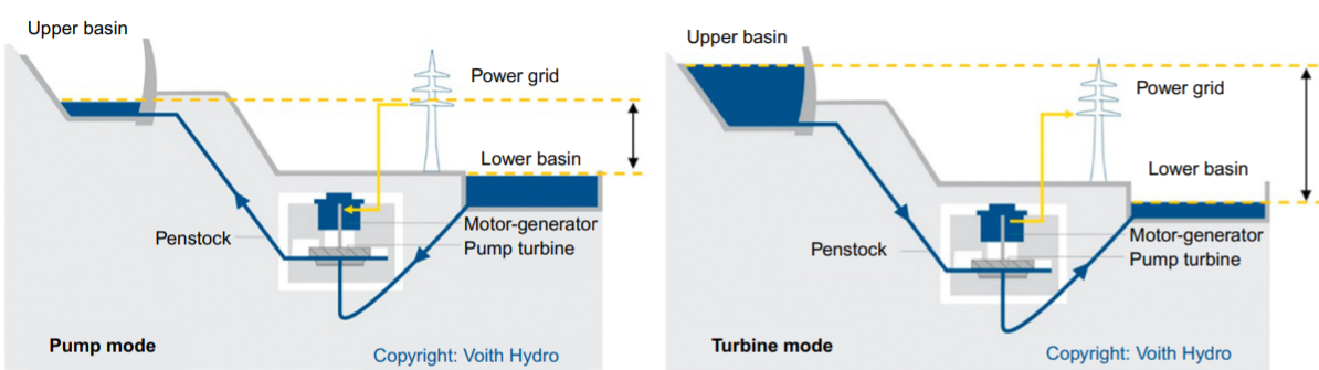
Pumped hydro-storage systems stock electricity using the gravitational potential energy of water. As shown in the following figure, the basic principle of energy conversion in this system relies on the movement of water from a higher to a lower point.
The system functions in two schemes, the first one is ‘’pump scheme’’ (charging), in which electrical energy is provided from the electrical grid during low-cost, off-peak surplus electric power periods in order to feed a motor that mechanically drives a pump, which elevates water from the lower basin to the upper one. The second one is ‘’turbine scheme’’ (discharging), in which the water simply flows downhill via gravity (from the upper basin to the lower one) and drives a turbine, that then drives mechanically the generator rotor producing electrical energy that returns to the electrical grid during periods of peak demand. (Source: researchgate.net: Thermal, Mechanical, and Hybrid Chemical Energy Storage Systems (pp.139-247), swri.org)
According to The World Energy Council, PHS systems have the following characteristics:
- Max power rating (MW): 3000
- Discharge time: 4h – 18h
- Max cycles/lifetime: 30 – 60 years
- Energy density (watt-hour per liter): 0.2 – 2
- Efficiency: 70 – 85% (Source: eesi.org)
Pumped hydro-storage data
First known uses of PHS were found in Italy and Switzerland in the 1890s. Now, PHS facilities can be found all around the world.
According to the 2021 edition of the Hydropower Market Report, PHS currently accounts for 95% of all utility-scale energy storage in the United States. (Source: energy.gov)
According to the International Hydropower Association, pumped storage hydropower is the world’s largest battery technology, accounting for over 94% of installed energy storage capacity, well ahead of lithium-ion and other battery types. IHA estimates that pumped storage hydropower (PHS) projects store up to 9,000 gigawatt hours (GWh) of electricity globally. (Source: hydropower.org)
According to the International Hydropower Association, pumped hydropower storage capacity in Europe was estimated 55 GW in 2020. (Source: hydropower.org)
The following figure gives global installed pumped storage hydropower capacity by region in 2019. In this figure we see that installed capacity In Europe that year was about 54 876 MW, approximately 55 GW.
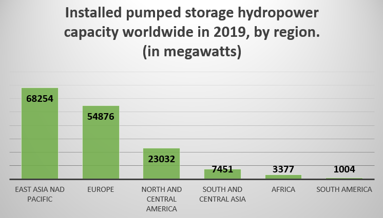
According to Statista, Italy had the highest installed capacity of pumped storage in Europe with about 7.69 gigawatts installed across the country in 2019. It was followed by France, with about 5.84 gigawatts of pumped storage capacity. (Source: statista.com)
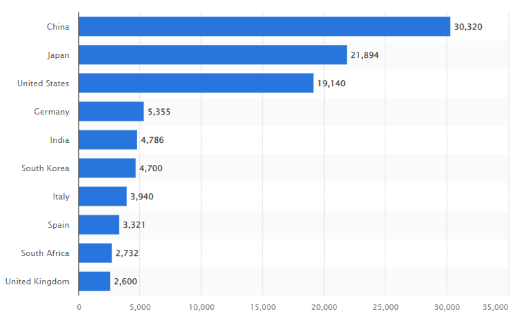
The following figure gives global installed pumped hydro-storage capacity by country in 2020.
According to Maximize Market Research, the global hydro-pumped storage plants market is estimated to witness high growth over 2019-2027, due to an increase in electricity demand in various countries. (Source: maximzeresearch.com)
Flywheel energy storage systems (FESS)
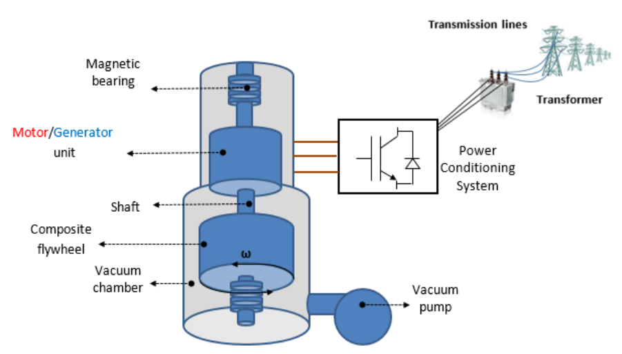
A Flywheel Energy Storage System is a mechanical device that consists of a mass rotating around an axis to enable energy storage in the form of kinetic energy.
The inbuilt motor of this energy storage system uses electrical power to turn at high speeds to set the flywheel turning at its operating speed, enabling kinetic energy storage. When energy is required, the flywheel transfers rotational energy to the motor that functions as a generator in this case. The rotational energy is thus converted back into electrical energy, completing the cycle.
The amount of energy available and its duration is controlled by the mass and speed of the flywheel. (Source: eepower.com, azocleantech.com)
The following figure gives the schematic diagram of a flywheel energy storage system.
According to The World Energy Council, FESS have the following characteristics:
- Max power rating (MW): 20
- Discharge time: sec- mins
- Max cycles/lifetime: 20000 – 100000
- Energy density (watt-hour per liter): 20 – 80
- Efficiency: 70 – 95% (Source: eesi.org)
Flywheel energy storage systems data
- The global flywheel energy storage system market size was valued at USD 312.1 million in 2019 and is expected to grow at a compound annual growth rate (CAGR) of 7.4% from 2020 to 2027. (Source: grandviewresearch.com)
- Inkwood Research estimates that the global market for flywheel energy storage will grow at a CAGR of 7.50% in terms of revenue and 8.32% in terms of volume during the 2020- 2028 forecast period, reaching a revenue of $570.74 million, and in terms of volume, 310.06 Kilo Watt, by 2028. The base year for the market study is 2019, while the forecast period is between 2020 and 2028. (Source: inkwoordresearch.com)
- The European flywheel energy storage market is anticipated to grow considerably and reach a record CAGR of 9.18% in terms of volume, and 7.80% in terms of revenue during the projected period of 2020-2028. (Source: inkwoodresearch.com)
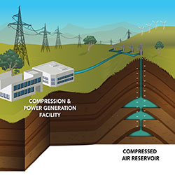
The following figure illustrates the working principle of a CAES system.
Liquid Air Energy Storage (LAES)
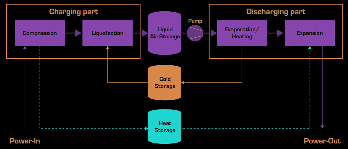
A Liquid Air Energy Storage (LAES) system, also referred to as Cryogenic Energy Storage (CES), can provide large-scale, long-term energy storage with hundreds of megawatts of output. The system comprises a charging system, an energy storage tank and a discharging system (as shown in the figure below). The charging system is an industrial air liquefaction plant where electrical energy is utilized to cool ambient air drawn from the environment until it liquifies (“cryogen”), the liquid air is then stored in an insulated tank at low pressure.
When power is needed, the discharging system functions by drawing liquid air from the tank. The air is then pumped to high pressure and evaporated, producing gaseous air that can be used to drive a piston engine or turbine to generate electricity. (Source: ease-storage.se, man-es.com)
The following figure shows the functioning principle of LEAS system.
The main components of a liquid air energy storage system are:
- Compressors (integral to the liquefaction unit) driven by an electric motor.
- Liquefaction unit.
- Low pressure, insulated liquefied air-tank.
- Evaporation unit.
- Air expander.
- Gas turbine (Optional).
- Electric generator.
- Cold Storage (Optional).
- Heat Storage (Optional). (Source: ease-sotage.se)
As shown in the above figure, cold storage and heat storage systems can be integrated into the LEAS process in order to increase efficiency. During discharge, very cold air is released and captured by a proprietary high-grade cold store, so it can be recycled during the liquefaction process to enhance the efficiency of the process. Alternatively, the system can integrate waste cold from industrial processes such as LNG terminals. Whilst, during the liquification process of the air heat is released and can be stored to be reused in the discharging phase. The system can also integrate waste heat from industrial processes, such as thermal power generation or steel mills. (Source: energystorage.org)
According to the Institute for Mechanical Engineers (IMechE), the LEAS process is about 25% to 70% efficient, which means that up to 70% of the electricity used to liquify the air can be recreated. (Source: thegreenage.co.uk)
Liquid air energy storage data
- According to the 2021 Liquid Air Systems Market Size, Status and Market Insights, Forecast to 2025 report, the global LEAS market size is expected to gain market growth in the forecast period of 2021 to 2025, with a CAGR of 74.6% increasing from USD 82 million in 2019 to USD 762.9 million by 2025. (Source: wboc.com)
- According to the Liquid Air Energy Storage Systems Market report (2021-2027), the global Liquid Air Energy Storage Systems market size is projected to reach USD 1612.2 million by 2027, from USD 147.1 million in 2020, at a CAGR of 35.4% during 2021-2027. (Source: marketwatch.com)