Electrochemical energy storage systems are the most traditional of all energy storage devices for power generation, they are based on storing chemical energy that is converted to electrical energy when needed. EES systems can be classified into three categories: Batteries, Electrochemical capacitors and fuel Cells. (Source: digital-library.theit.org)
Battery energy storage systems (BESS)
Electrochemical batteries consist of electrochemical cells that convert stored chemical energy into electrical energy. (Source: energyfaculty.com)
Rechargeable batteries (secondary batteries)
Rechargeable batteries are one of the oldest technologies for electrical energy storage (EES) systems, they are extensively used for daily needs and in numerous industrial applications. Electrochemical batteries are made of electrochemical cells that consist of electrodes made up of different types of metals that are submersed into liquid or solid electrolytes.
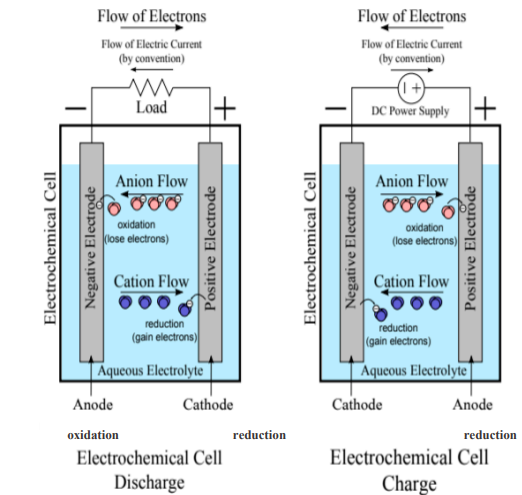
The basic functioning principle of electrochemical batteries is as follows:
A flow of electrons travels from the negative electrode (anode) to the positive one (cathode), until the anode runs out of electrons. In the case of primary batteries, the process ends here. Whereas for secondary batteries that are rechargeable, this reaction can be reversed using a charger. The electrons will flow from the cathode back to the anode, restoring the initial excess of electrons in the anode. (Source: mdpi.com, Panasonic-eneloop.eu)
The flow of electrons originates from reduction-oxidation chemical reactions that occur in the electrochemical cell; these are commonly called redox reactions and in the case of an electrochemical cell, one half-reaction occurs in each electrode.
Oxidation is the loss of electrons and is the reaction that occurs in the anode, the electrode reacts with the electrolyte producing electrons and we say that the anode is oxidized. Whilst, reduction is the gain of electrons, and is what occurs simultaneously in the cathode, enabling it to accept electrons and we say that the cathode is reduced.
During the discharge cycle, the positive electrode is the cathode and the negative electrode is the anode, electrons flow from the anode to the cathode generating electricity. Whereas, during the charging cycle the reverse reaction happens and the positive electrode is the anode and the negative electrode is the cathode. As shown in the following figure. (Source: mdpi.com)
Types of rechargeable batteries
Depending on their chemistry, we can distinguish the main following types of rechargeable batteries.
Lead-acid (PbA) batteries
Lead-acid batteries are the oldest type of rechargeable batteries and one of the cheapest most available solutions that are widely used in automotive sector, industrial applications and power storage systems. They are highly recyclable, their chemistry is considered mature, robust and well understood and are considered one of the most technologically developed and commercially successful battery systems. (Source: mdpi.com, adb.org)
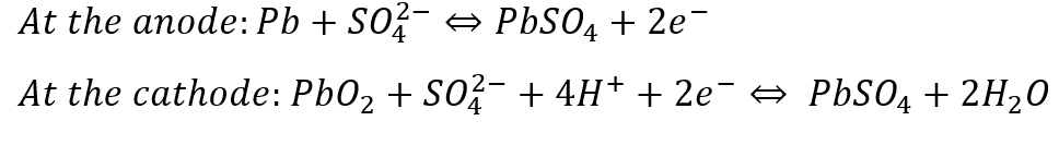
In a Pb-A battery cell, PbO2 is used as the cathode and Pb as the anode and sulfuric acid is used as the electrolyte. The redox reactions that occur in both the anode and the cathode are: (Source: mdpi.com)
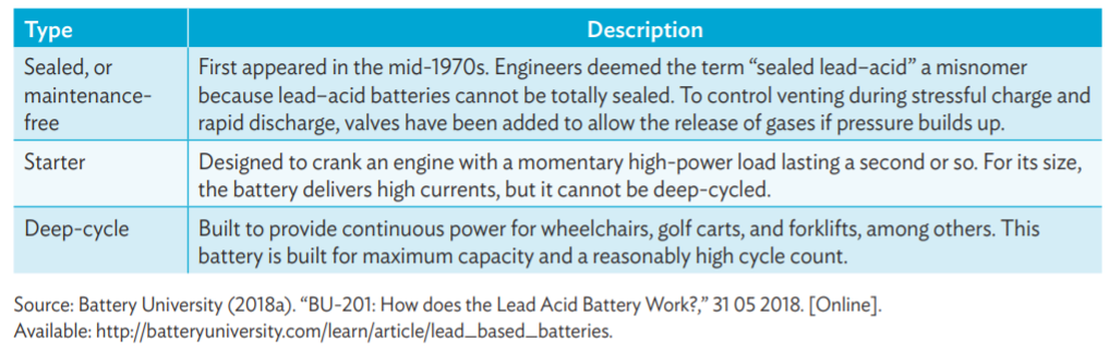
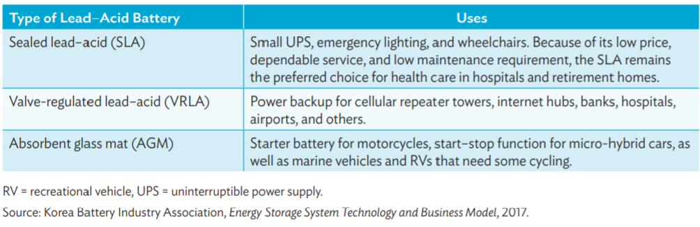
The following tables give types of lead acid batteries and their use.
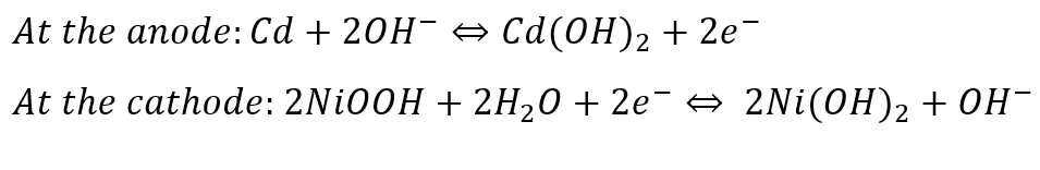
Nickel-Cadmium (Ni-Cd) batteries
Nickel-cadmium batteries (Ni-Cd) are utilized for portable computers, drills, camcorders, and other small battery-operated devices. Nickel-cadmium batteries can be found in two distinctive designs, a completely sealed cell and a vented cell to release gases (oxygen and hydrogen). Sealed cells are used in daily life whilst vented Ni-Cd batteries are used in aircraft and diesel engine starters, where large energy per weight and volume are critical. (Source: adb.org, mdpi.com)
Reactions occurring at the anode and the cathode are: (Source: mdpi.com)

Nickel–Metal Hydride (Ni–MH) Battery
Ni–MH batteries outperform other rechargeable batteries, and have higher capacity and less voltage depression. These batteries are largely used in high-end portable electronic products, in which battery performance parameters, notably run time, are major considerations in the purchase decision. (Source: adp.org)
Reactions occurring at the anode and the cathode are: (Source: mdpi.com)
Flow batteries energy storage (FBES)
Flow batteries or redox flow batteries (RFB) are a category of electrochemical energy storage devices consisting of two liquid electrolyte tanks connected to a cell stack separated by an ion selective membrane. Electrolytes are drawn from the tanks to the cell stack where the process is based on reduction-oxidation reactions of the electrolyte solutions to achieve charging and discharging of batteries. During the charging process, PV panels, wind turbines, or grid input is used to provide electrons to recharge the electrolyte. In the discharging process, the liquid electrolyte is pumped through electrodes to extract the electrons and to generate electricity.
Several types of electrolytes have been used in flow batteries such as zinc (ZnBr), sodium (NaBr), vanadium (VBr) and, more recently, sodium polysulfide. (Source: sciencedirect.com, mdpi.com)
The following figure illustrates a flow battery.
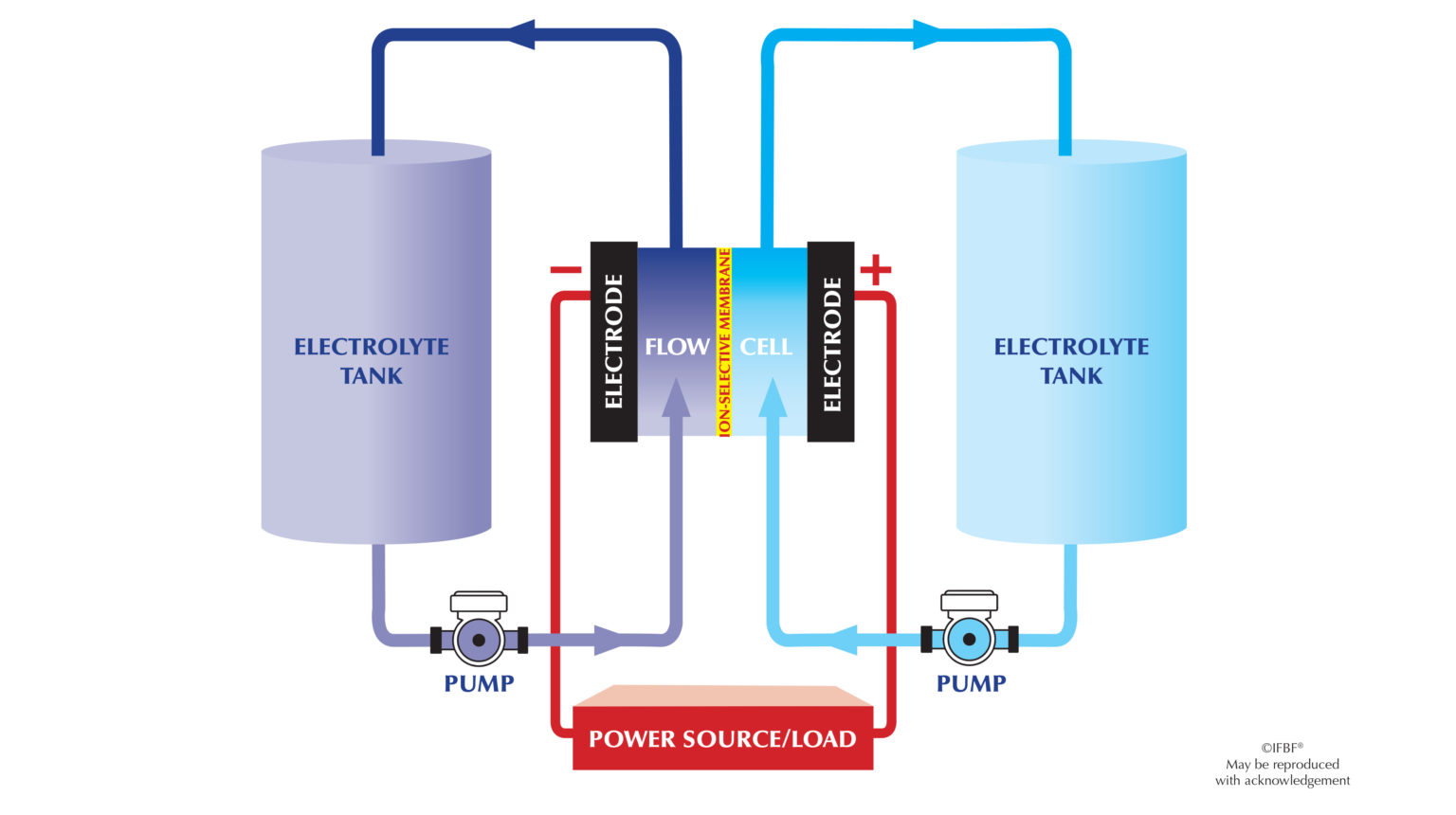
Flow batteries technology is well established and proven to be ideal for long-duration energy output with very low degradation of components within larger, utility-scale deployments and life spans reaching up to 30 years, depending on the electrolyte chemistry. Flow batteries can overcome the limitations of standard electrochemical accumulators (lead–acid or nickel–cadmium for instance) in which the electrochemical reactions create solid compounds that are stored directly on the electrodes on which they form, making them a limited-mass system, that limits the capacity of standard batteries. (Source: powermage.com, sciencedirect.com)
Supercapacitors store charge either using electrostatic double-layer capacitance (EDLC) or electrochemical pseudo-capacitance or both known as hybrid capacitance. (Source: electricaltechnology.org)
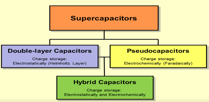
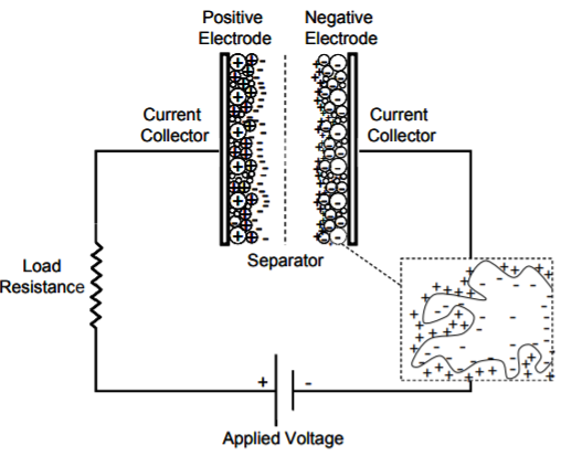
Electrochemical Double-Layer capacitors
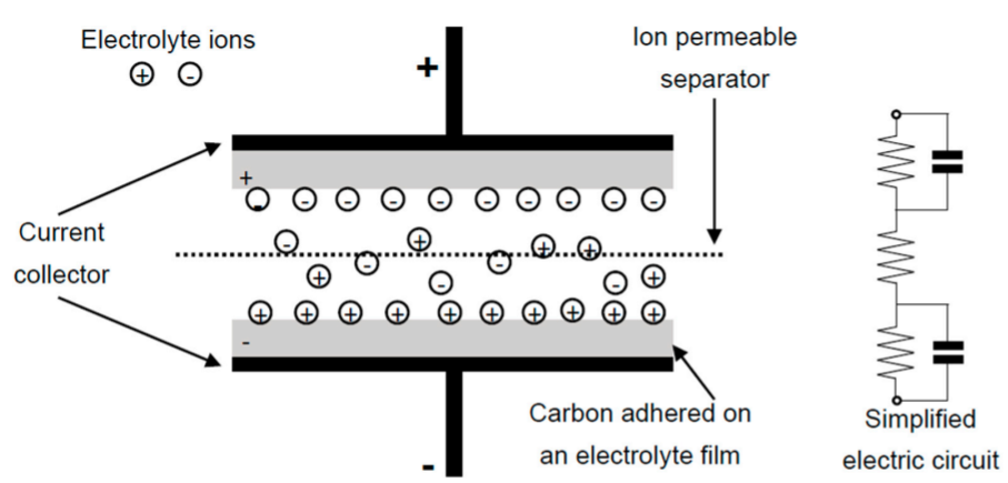
Electrochemical double-layer capacitors (EDLCs) are constructed from two carbon-based electrodes, an electrolyte, and a separator and they utilize an electrochemical double-layer of charge to store energy. As a conventional capacitor, in EDLCs there is no transfer of charge between electrode and electrolyte and charge is stored electrostatically (non-Faradaically).
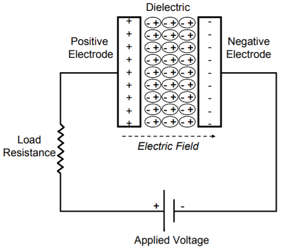
When voltage is applied, charge accumulates on the electrode surfaces. Following the natural attraction of unlike charges, ions in the electrolyte solution diffuse across the separator into the pores of the electrode of opposite charge. However, the electrodes are engineered to prevent the recombination of the ions. Thus, a double-layer of charge is produced at each electrode, as shown in the following figure. These double-layers, coupled with an increase in surface area and a decrease in the distance between electrodes, allow EDLCs to achieve higher energy densities than conventional capacitors. (Source: mitre.org)
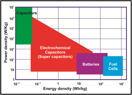
Electrochemical capacitors have relatively high-power densities, but relatively low energy densities when compared to electrochemical batteries and to fuel cells. A battery can store more total energy than a capacitor, but it cannot deliver it very quickly, which means its power density is low. Capacitors, on the other hand, store relatively less energy per unit mass or volume, but can discharge it rapidly to produce a lot of power, so their power density is usually high. (Source: mitre.org)
The following figure gives comparison of batteries, ECs and fuel cell energy and power density. (Source: sciencedirect.com)
Electrochemical energy storage data
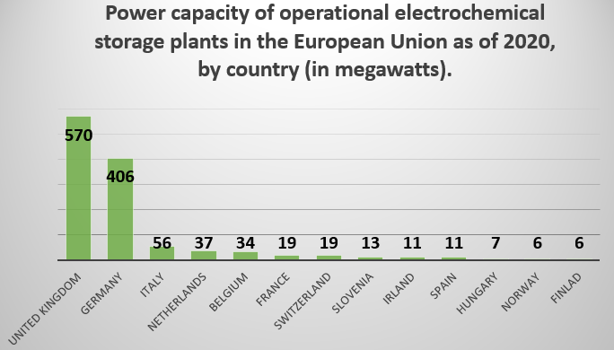
According to Statista’s operational electrochemical storage power capacity in the EU 2020, by country article, the United Kingdom has the highest power capacity of operational electrochemical storage facilities in European countries, at 570 megawatts. With the UK formally leaving the European Union in January 2020, Germany is currently the EU member state with the highest operational electrochemical storage power capacity, at 406 megawatts. (Source: statista.com)
The following figure gives power capacity of operational electrochemical storage plants in the European Union as of 2020.
According to Marketsandmarkets, the global fuel cells market size is expected to reach USD 848 million by 2025 from an estimated value of USD 263 million in 2020, growing at a CAGR of 26.4%. The market has been analyzed with key focus on advancements in fuel cell technologies such as PEMFC, PAFC, AFC, and MFC. The growth is due to the rising demand for clean energy generation in developed regions, increased use of fuel cell-based vehicles, booming power sector, and augmented power generation capacities globally. (Source: marketsandmarkets.com)
According to Battery Energy Storage System, Update 2021 – Global Market Size, Competitive Landscape, Key Country Analysis to 2025 report, Asia-Pacific (APAC) was the largest market for battery energy storage systems in 2020, accounting for 49.9% of the global market installed capacity. The region is forecast to maintain its top position in the forecast period up to 2025, as well as its market share of approximately 53.5% in 2025, followed by Europe, Middle East and Africa (EMEA) and the Americas. (Source: store.globaldata.com)
According to Global Supercapacitor Market with COVID-19 Impact Analysis by Type, Electrode Material, Application, Region – Global Forecast to 2025 report, the Supercapacitor market is projected to grow from USD 409 million in 2020 to USD 720 million by 2025; it is expected to grow at a CAGR of 12.0% from 2020 to 2025. This growth is driven by their increasing demand on energy harvesting applications and rising use of supercapacitors in trains and aircraft. Moreover, the increasing global demand for electric vehicles is likely to fuel the growth of the market. (Source: marketsandmarkets.com)